Composite Insulators (Polytek)

Experience Matters
Put More Than 25 Years of Polymer Experience to Design Composite Insulators
With a rich experience of more than 25 years in the field of Heat Shrinkable Technology, was quick to identify the benefits of using similar concept for composite polymer insulator technology to replace traditional materials such as Glass or Porcelain for Insulators. As a result of continued efforts and research a unique Polyolefin cladding material formulation have been evolved which is cross linked Polymer with excellent outdoor performance and other desired properties needed for installations of insulators in outdoor conditions.
Combined the technology of this high Performing Polymer material with high mechanical strength fiberglass reinforced rod and metal end fittings to produce a high quality Polytek composite Polymeric insulator for various end applications.
Insulators Design Concept (Unibody Design& Modular Design)
Unibody Design : insulators are one-piece injection molded directly to the rod and sealed to the end fittings with a bead of silicone to give the insulator high dielectric strength and protect it from all environmental conditions. This design is used for standard distribution dead end/ suspension insulators and Station/Post Insulators.
Modular Design : provides complete versatility for composite insulators. Individual molded weather sheds are assembled to the rod to meet specific length or electrical requirements. A high dielectric strength silicone gel is used as an interface.

Weather sheds and Coverings : The design covers for two options for housing elastomer which can either be Cross-linked Polyolefin or Silicone Rubber depending on customer preference. Both Elastomer housing is shown to defy the damaging effects of ultraviolet rays, Ozone, acid, contamination and moisture.
Fiberglass Rod : A high quality, corrosion resistant, fiberglass reinforced rod is the core of every insulator with ultimate mechanical strength at least twice the maximum working load.
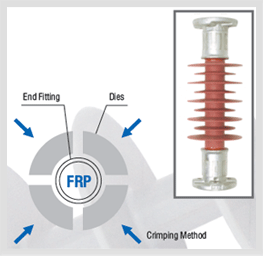
End Fittings : Standard distribution dead/end suspension units are supplied with clevis and tongue fittings. Ball, socket, and eye fittings are also available. All are made of hot dipped galvanized high strength Carbon Steel (Stainless Steel available upon request). All end fittings on dead/end suspension insulators are attached by compression. A new developed crimping control technology monitors the assembly process of the metal fittings and ensures that crimping forces cause no damage to the fiberglass rod while achieving a crimp that will withstand the highest possible mechanical loads. Every insulator is proof tested to verify the crimp. Post and station Insulators fittings have a unique design. For railway applications, tension and strut composite insulators are available in a large variety of configurations.
Key Features
- Long Life
- Suitable for polluted environments, salty atmospheres etc.
- Unique self cleaning property
- Resistance to breakage and vandalism, practically unbreakable
- Superior anti-tracking properties
- High mechanical strength
- Light weight
- Ease of installation
- Choice of end fittings
- Long term surface hydrophobicity
- Compliance with IEC 61109, CEA LWIWG-01(91), ANSI C29.11-1989
Shape for Optimum Performance of Insulators
The exterior appearance of a high-voltage insulator depends on a combination of various factors determining its specific shape. Designing an Insulator for optimum performance requires an exact knowledge and description of all application needs. Polytek Insulator design considers following design criteria to ensure excellent field performance and ZERO DEFECT end product.
Mechanical requirements
The mechanical forces such as bending moments, compression, tension, torsion, etc. acting on the insulator and its connecting system must be accurately specified.
Electrical Characteristics
Data such as the lightning impulse flashover voltage, switching impulse flashover voltage and power-frequency flashover voltage define the necessary dielectric strength and insulator length.

Creepage distance requirements
Creepage distances are defined in accordance with IEC 60815 and with customers' requirements.
Applicable standards and testing codes
International standards, codes and test specifications are observed in the manufacture of the product. The design comply with IEC 61109 with up dated ammendments.
Customer specifications and installation requirements
Special requirements (connecting dimensions, diameter, etc.) are considered during design.
Environmental conditions
Environmental conditions at the installation site determine the design and number of insulator sheds
Typical Design Data
10 - 15 kv Composite Insulators
- Nominal pulse System Voltage kV
- Min. Creepage Distance mm
- Section Length mm
- Rated Mechanical tensile load kN
- Wet power freq. 1 min. withstand voltage kV
- Dry lighting impulse withstand voltage kV
- 11
- 307
- 274
- 45
- 35
- 75
- 11
- 450
- 430
- 70
- 48
- 100
- 11
- 360
- 330
- 70
- 42
- 100
- 11
- 450
- 430
- 100
- 48
- 100
- 11
- 500
- 430
- 100
- 48
- 100
- 11
- 450
- 430
- 100
- 48
- 100
- 13
- 415
- 341
- 70
- 70
- 100
- 13
- 418
- 360
- 70
- 35
- 100
22 - 28 kv Composite Insulators
- Nominal pulse System Voltage kV
- Min. Creepage Distance mm
- Section Length mm
- Rated Mechanical tensile load kN
- Wet power freq. 1 min. withstand voltage kV
- Dry lighting impulse withstand voltage kV
- 33
- 810
- 650
- 70
- 80
- 170
- 33
- 1050
- 650
- 70
- 85
- 230
- 33
- 1012
- 628
- 70
- 85
- 230
- 33
- 851
- 536
- 70
- 85
- 170
- 33
- 1050
- 680
- 70
- 85
- 230
- 33
- 810
- 610
- 70
- 80
- 170
- 33
- 810
- 650
- 80
- 80
- 170
- 33
- 1015
- 610
- 80
- 85
- 230
- 33
- 1015
- 610
- 80
- 85
- 230
- 33
- 1015
- 650
- 80
- 85
- 230
- 33
- 854
- 532
- 95
- 85
- 170
- 33
- 815
- 440
- 100
- 80
- 170
- 33
- 1146
- 550
- 70
- 85
- 215
- 33
- 817
- 397
- 70
- 80
- 170
- 33
- 817
- 397
- 70
- 80
- 170
- 33
- 735
- 405
- 70
- 80
- 170
- 33
- 927
- 429
- 70
- 80
- 220
- 33
- 880
- 660
- 100
- 80
- 230
- 33
- 1015
- 660
- 100
- 85
- 230
33 - 36 kv Composite Insulators
- Nominal pulse System Voltage kV
- Min. Creepage Distance mm
- Section Length mm
- Rated Mechanical tensile load kN
- Wet power freq. 1 min. withstand voltage kV
- Dry lighting impulse withstand voltage kV
- 22
- 603
- 425
- 60
- 60
- 140
- 22
- 568
- 333
- 65
- 60
- 140
- 22
- 850
- 444
- 70
- 60
- 140
- 22
- 635
- 444
- 70
- 60
- 140
- 22
- 580
- 349
- 70
- 60
- 140
- 22
- 817
- 397
- 70
- 60
- 100
- 22
- 580
- 349
- 80
- 60
- 140
- 22
- 708
- 365
- 80
- 60
- 140
- 22
- 657
- 378
- 80
- 60
- 160
- 22
- 622
- 458
- 95
- 60
- 160
- 22
- 850
- 444
- 100
- 60
- 140
- 23
- 645
- 442
- 70
- 70
- 204
- 25
- 643
- 451
- 70
- 110
- 200
Key Features
-

Composite Insulators Installed in Transmission lines

Composite Polymeric Insulators with Optional End Fittings
-

Outdoor Termination installed over a single pole using polymeric insulators for isolation to avoid phase to earth short circulting

Complosite polymeric insulators (ball/socked) tansion insulator in contrast with traditional porcelain disc type insulators.
-

Polymeric Insulators installed in outdoor switch disconnector.

Polymeric Insulators installed in outdoor Disconnector.
Products
Heat Shrinkable Moulded Shapes
Heat Shrink Tubes / Heat Shrink Sleeves
- Advantages Of Heat shrink Tubing
- Thin Wall Tubes
- GDW : Dual Wall Tubing
- Medium/Heavy Wall Tubes-Commercial
- Heat Shrink Co-extruded Tubing Premium Quality
- Red Insulation Tubes
- Non Tracking Tubes
- Busbar Sleeves
- Stress Control Tube
- Integrated Stress Control Tube-GVOT Tube
- Heat Shrink Double Layer Tube-GDTL Tube
- High Shrink Ratio Heat Shrink Tube
Switchgear Insulation Products
- Barrier Board Sheet
- End Sealing Kit for Extensible RMU/GIS Bushing
- Heat Shrink Bus Bar Sleeve
- Bus Bar Insulating Shrouds
- Bus Bar Insulating Shrouds Polyolefin
- Bus Bar End Caps
- Thin wall tube wire marking
- Heat Shrink Tape (Bustape)
- Insulation for Circuit Breakers
- Busbar Sleeve for 66 kV
- Bushing Boot
- Non Shrinkable High Voltage Tape
- Heat Shrinkable Gland


